
This post is a continuation of Part 1 on How to Adjust Car Valves. Lately, we have gone through the role of car valves.
We will now cover:
– When to adjust the valves?
– Step 1: Prepare your vehicle
– Step 2: Case 1: Check valve lash with an overhead camshaft
– Step 2: Case 2: Check the valve clearance using a screw and lock nut system
When to adjust the valves?
The adjustment of the valves is justified in different cases:
– Appearance of metallic noises during hot or cold operation, located in the camshaft area.
Good to know: precisely locate an engine noise using a large screwdriver applied to the suspect areas. The sound is amplified (stethoscope effect) by bringing the ear closer to the handle.
– Difficulty starting. Valves with insufficient clearance are “flanged.” They are not watertight when closed, which means that the engine lacks compression.
Good to know: an engine compression test can be carried out beforehand to validate the diagnosis.
Step1: Prepare your vehicle
– Identify the tuning system by obtaining the technical review dedicated to your car.
Good to know: the technical review allows you to know the technology used for your engine, its tuning method and the various preliminary operations for accessing the tuning.
– Work on a cold engine (unless otherwise specified by the manufacturer).
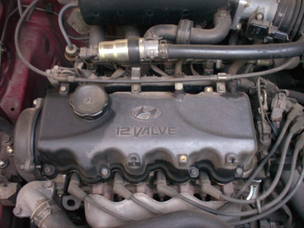
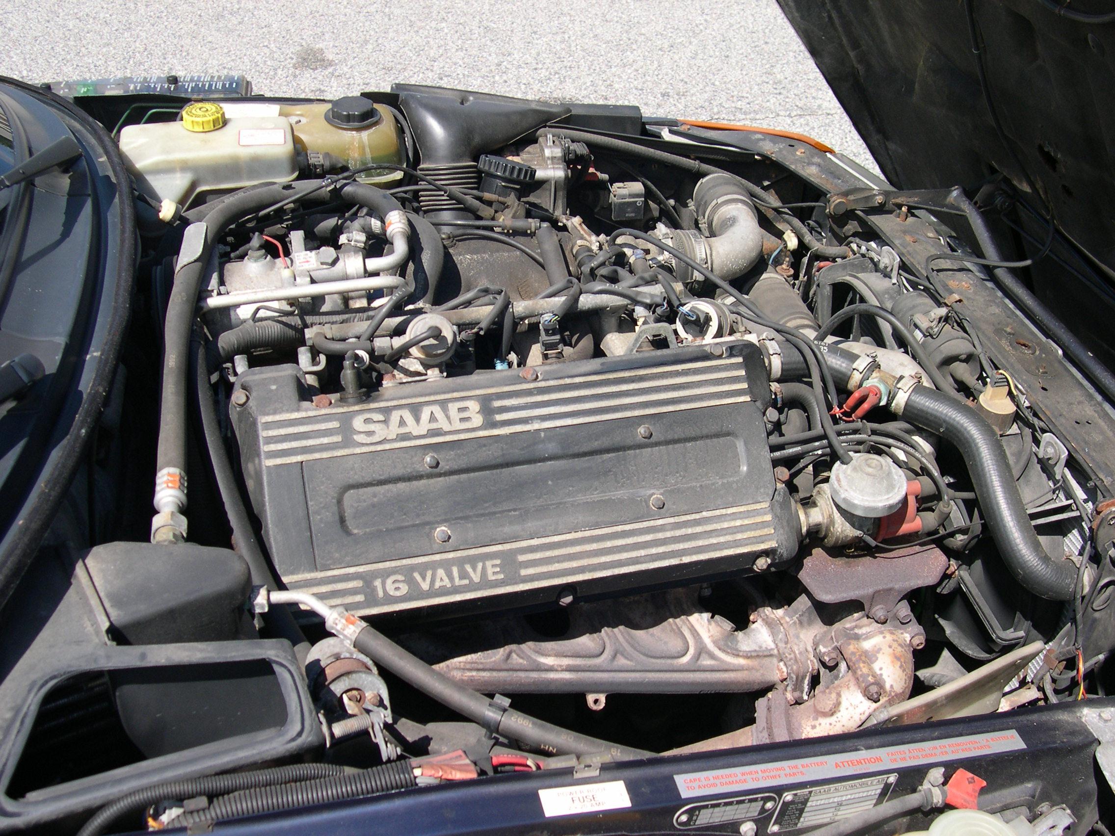
– Remove the upper engine crankcase (cylinder head or rocker covers).
– Lift the wheel on the front right side of the vehicle with a jack.
– Secure the workstation by adding a wheel chock.
Good to know: in the case of an engine coupled to an automatic transmission, you are obliged to drive the engine with a wrench through the crankshaft pulley’s nut.
Step 2: Case 1: Check valve lash with an overhead camshaft
This situation corresponds to a pellet setting.
The aim is to position the camshaft, which is visible, in such a way that the valve to be controlled is not constrained by it: the cam of the shaft must therefore point away from the tappet.
– Turn the engine by the wheel until the cam is correctly positioned.
– Using a set of shims, measure the clearance between the cam and the tappet. To do this, select the shim that slides without play but without forcing.
Good to know: you can add several shims to find the exact thickness, their gauge ranges from 0.04 mm to 1.20 mm.
– Repeat the process for all valves and note the value you find each time.
Step 2: Case 2: check the valve clearance using a screw and lock nut system
In this case, the camshaft is often not visually accessible. Engine positioning for each valve can be done in two ways (4-cylinder engine).
Use the so-called “balancing” method
This method allows the inlet and exhaust valve of the same cylinder to be adjusted simultaneously.
Turn the engine until the opposite cylinder’s valves are balanced: the exhaust valve will finish closing, and the intake valve will start opening.
– Check the valve clearance of the cylinder between the valve stem and the rocker arm.
◦ When cylinder 1 is in the balance position, check the intake and exhaust valves of cylinder 4.
◦ When cylinder 3 is in balance, check the valves of cylinder 2.
◦ When cylinder 4 is in balance, check the valves on cylinder 1.
◦ When Cylinder 2 is in balance, check the valves on Cylinder 3.
Apply the “full opening” method
Another solution to bring the valves to the setpoint is the “full opening” method.
– Position each exhaust valve in turn to full opening (fully depressed by the cam).
– Check the corresponding valves.
◦ When the Cylinder 1 exhaust valve is set to fully open, check the Cylinder 3 intake valve’s clearance and the Cylinder 4 exhaust valve’s clearance.
◦ With Cylinder 3 exhaust valve in the fully open position, check the inlet valve’s clearance on Cylinder 4 and the clearance of the exhaust valve on Cylinder 2.
◦ With the cylinder 4 exhaust valve fully open, check the clearance of the cylinder 2 intake valve and the cylinder 1 exhaust valve’s clearance.
◦ With Cylinder 2 exhaust valve fully open, check the inlet valve’s clearance on Cylinder 1 and the clearance of the exhaust valve on Cylinder 3.
Good to know: These settings are valid for engines with ignition order 1-3-4-2.
This post will now continue in part 3 in our next publication. Stay posted, and remember to leave your comments below.


3 thoughts on “How to Adjust Car Valves (Part 2)”